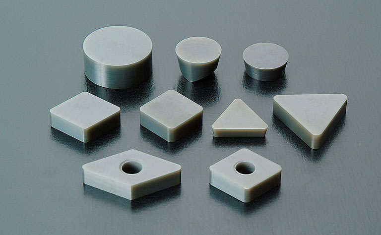
 CutterFor machining heat-resistant alloys | Ceramic
NTK's Pursuit of the Ultimate Cutter's Birth
Introducing a New Paradigm in Ceramic-Embedded Cutters
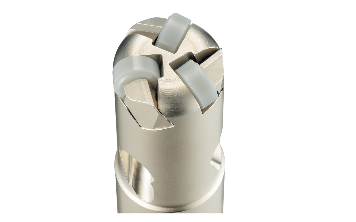
NTK Achieves Industry-First Triple-Blade Configuration with Ceramic Negative Inserts for φ.630″ Cutters
By utilizing double-sided, high-strength negative inserts and the high efficiency of three blades,
NTK contributes to cost-effective tooling, stable machining processes, and enhanced productivity.
Features
- Enhancing Machining Efficiency Further with Increased Insert Count
- Economical with Double-Sided Usable Negative Inserts
- Extended Lifespan Chipbreaker
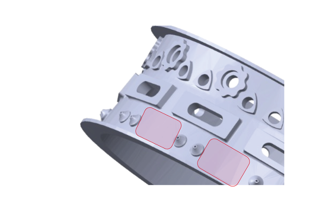
Tooling application
Milling
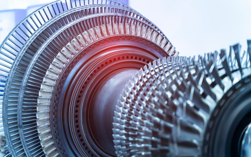
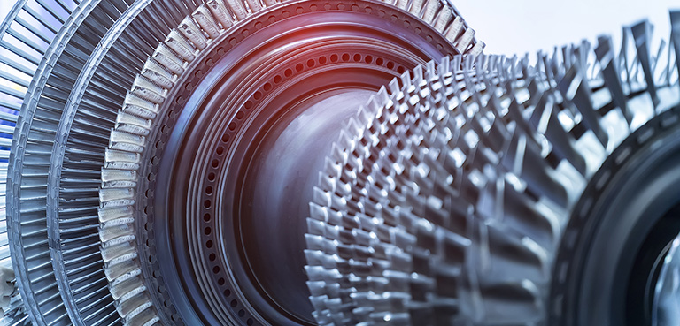
For aircraft parts / generator parts
Enhancing Machining Efficiency Further with Increased Insert Count
High-E ciency Machining with 3-insert Design at .630″ - Supports Maximum Table Feed of 283 ipm
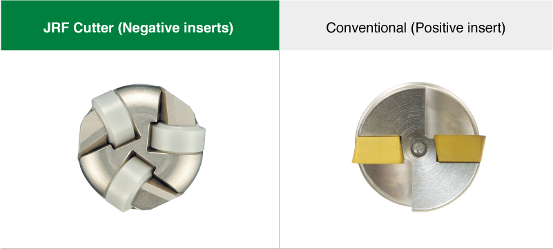
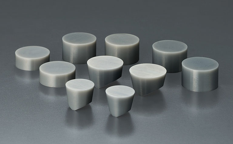
Economical with Double-Sided Usable Negative Inserts
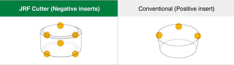
🟡 Available corners
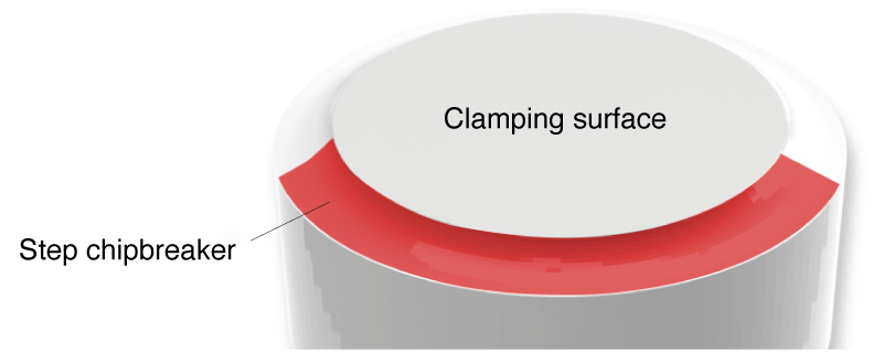
Extended Lifespan Chipbreaker
Our Step Chipbreaker: Reduces Flaking by Lowering the Cutting Edge from the Clamping Surface of Conventional (Positive Insert) Tools.
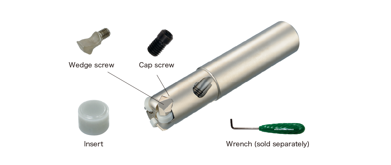
Prevent Insert Movement During Machining with Increased Clamping Force
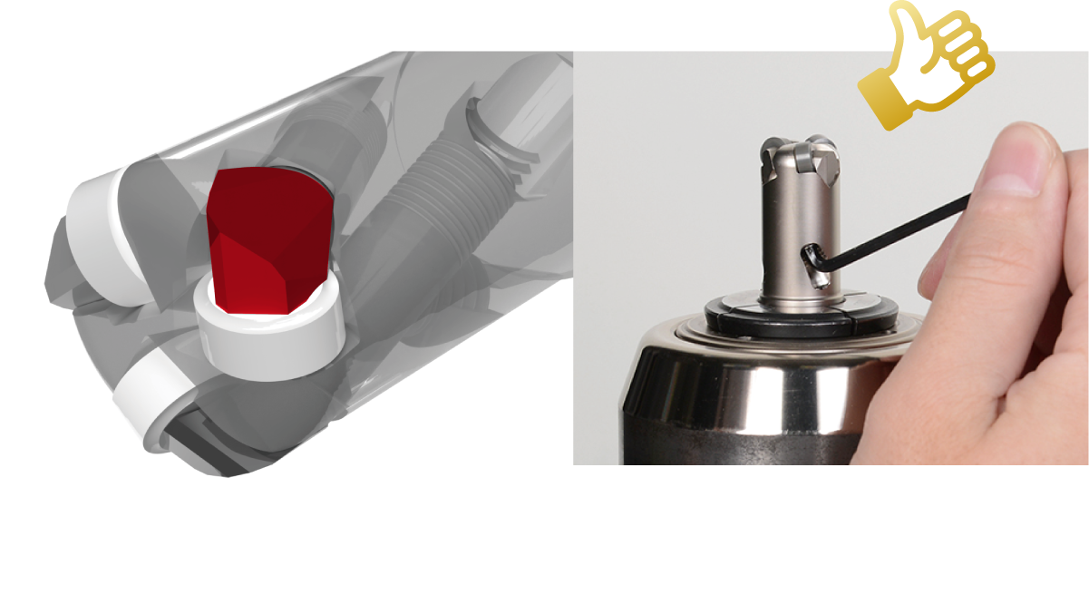
New clamp system (φ .630″)
Parts installation procedure video
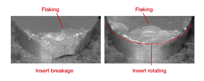
Insert Damage Suppression with Chipbreaker-Equipped Negative Inserts and Increased Clamping Force!
| Waspaloy (Combustion Casing) | ||
|---|---|---|
| JRF Cutter ( Negative insert) | Competitor (Positive insert) | |
| Number of teeth | 3 ( Φ.630″ ) | 2 ( Φ.630″ ) |
| Table feed (ipm) | 88 | 59 |
| Edge Damage | 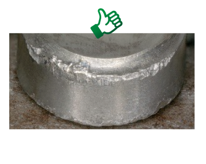 |
 |
- [ Cutting condition ]
- 1640SFM Feed per tooth (ipt)= .0030″ D.O.C.= .0197″
Recommended Cutting conditions
Scroll the table →
| Grade | Material | Operation type | Cutting speed (sfm) | Feed (ipt) | DOC (inch) | Coolant |
|---|---|---|---|---|---|---|
| SX3 / SX9 | HRSA | Milling | 1300 - 2300 – 3280 | .0032 - .0039 - .0047 | - .0394 | DRY |
Allowable rotation speed
| Cutter Item number | Cutting edge dia | Tooth | Allowable rotation speed (min-1) |
|---|---|---|---|
| JRFMH016E160R03 | 16 | 3 | 20,000 |
| JRFIH0625E0625R03 | 5/8" | ||
| JRFMH020E200R03 | 20 | 17,500 | |
| JRFIH075E075R03 | 3/4" | ||
| JRFMH025E250R04 | 25 | 4 | 15,000 |
| JRFIH100E100R04 | 1.0" | ||
| JRFMH032E320R05 | 32 | 5 | 15,000 |
| JRFIH125E125R05 | 1.25" | ||
| JRFMH025E250R03 | 25 | 3 | 12,500 |
| JRFIH100E100R03 | 1.0" | ||
| JRFMH032E320R04 | 32 | 4 | 12,500 |
| JRFIH125E125R04 | 1.25" | ||
| JRFMH032E320R03 | 32 | 3 | 12,500 |
| JRFIH125E125R03 | 1.25" |
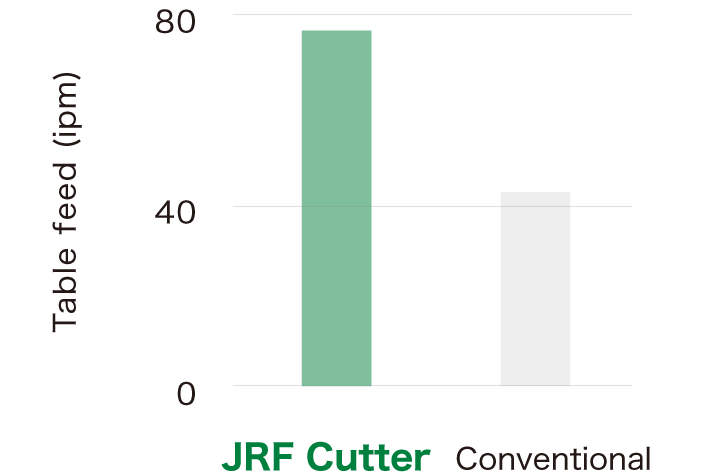
Case study
| Waspaloy(Combustion case) | ||
|---|---|---|
| JRF Cutter | Conventional | |
| Grade | SX9 Negative insert | SX9 (RP) Positive insert |
| Number of teeth | 5 (Φ1.25") | 3 (Φ1.25") |
| Speed (sfm) | 2624 ( 8,000rpm ) | 2624 ( 8,000rpm ) |
| Feed per tooth (ipt) | .002 | .002 |
| Table feed (ipm) | 78 | 47 |
| D.O.C. (inch) | .0394 | .0394 |
| Tool life | 2 Pass | 1 Pass |
| Number of usable corners | 8 | 5 |
 |
 |
| Cost Productivity | |
| NTK | 68% ← |
|---|---|
| Conventional | 100% |
32% cost reduction!
Insert Price ÷ Number of Corners (tool life) x Number of inserts
Lineup
Scroll the table →
| Cutter Item number | Cutting edge dia | Tooth | Insert Item number | IC | Thickness | Cap screw | Wedge screw | Wrench (sold separately) |
|---|---|---|---|---|---|---|---|---|
| JRFMH016E160R03 | 16 | 3 | -SX3RNGF060300E-HNF -SX9RNGF060300E-HNF |
1/4" | 1/8" | HCS3P050 | HWS3P050 | DL-025-08-JRF |
| JRFIH0625E0625R03 | 5/8" | |||||||
| JRFMH020E200R03 | 20 | -SX3RNGF060400E-HNF -SX9RNGF060400E-HNF |
3/16" | |||||
| JRFIH075E075R03 | 3/4" | |||||||
| JRFMH025E250R04 | 25 | 4 | DL-025-20-JRF | |||||
| JRFIH100E100R04 | 1.0" | |||||||
| JRFMH032E320R05 | 32 | 5 | -SX3RNGF090400E-HNF -SX9RNGF090400E-HNF |
3/8" | ||||
| JRFIH125E125R05 | 1.25" | |||||||
| JRFMH025E250R03 | 25 | 3 | HCS5P080 | HWS5P080 | DL-040-20-JRF | |||
| JRFIH100E100R03 | 1.0" | |||||||
| JRFMH032E320R04 | 32 | 4 | ||||||
| JRFIH125E125R04 | 1.25" | |||||||
| JRFMH032E320R03 | 32 | 3 | -SX3RNGF120400E-HNF | 1/2" | ||||
| JRFIH125E125R03 | 1.25" |
Product video
Catalog
Contact
Other recommended products
-
SX3Roughing & semi-finishing heat resistant alloys | Sialon ceramic
First recommendation for heat resistant alloys machining
-
SX9Machines through scale on heat resistant alloys | Sialon ceramic
Excellent notch and flank wear resistant ceramic
-
SX5Machine heavy scale & interruptions on heat resistant alloys| Sialon ceramic
Toughest SiAlON ceramic on the market
-
SX7Roughing (no scale) to semi-finishing heat resistant alloys | Sialon ceramic
Wear resistant Sialon ceramic material
Useful information
 Points for maximizing the performance of ceramic insert〔 Milling roughness to semi-finishing of heat-resistant alloys 〕
 Points for maximizing the performance of ceramic insert 〔 Rough to semi-finish turning of heat-resistant alloys 〕
 Tips for effectively cutting nickel-based alloys by knowing the material’s characteristics
 How to Make Ceramic Cutting Tools from Scratch