NTK Cutting Tools

HPC Series

Milling tools for finishing aluminum alloys PCD inserts

High speed milling of aluminum

Wide range of sizes from ⌀20 to ⌀100 mm ⌀.787” to ⌀3.937

Fixed type / Adjustable type
  • Above : Shank type
  • Below : Shell type
  • Small diameter type

Features

  • A wide range of sizes The diameters range from φ20 – φ100 φ.787” – φ3.937” for the HPC series
  • Excellent rigidity (HPC) The material for the HPC body is steel, achieving exceptional reliability
Product video
Cutting of rocker shaft holder
Material :
ADC12 aluminum
Surface
roughness
standards :
12.5S
Surface
roughness :
1.5S
Cutting
specification :
φ 32 1.25” ×4 cutting edges (PD1)
φ 32 1.25” ×2 cutting edges (Competitor’s PCD)
Cutting speed :
800 m/min 2,600 SFM (PD1)
600 m/min 2,000 SFM (Competitor’s PCD)
Revolution :
8,000 min-1 (PD1)
6,000 min-1 (Competitor’s PCD)
Feed :
0.05 mm/t .002 ipt (PD1)
0.025 mm/t .001 ipt (Competitor’s PCD)
Table feed rate :
1,600 mm/min 63 ipm (PD1)
300 mm/min 12 ipm (Competitor’s PCD)
DOC :
MAX 1.0 mm .040 inch
Coolant :
WET (through coolant)
PD1
15,000 pcs / corner (Ongoing)
Competitor’s PCD
8000 pcs / corner

This cutter reduced the total cycle time by 3 minutes.

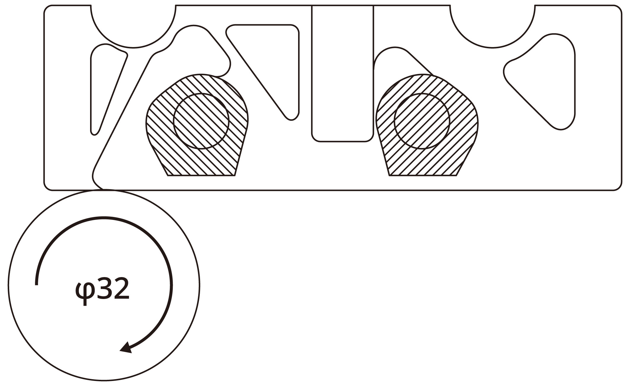
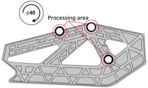
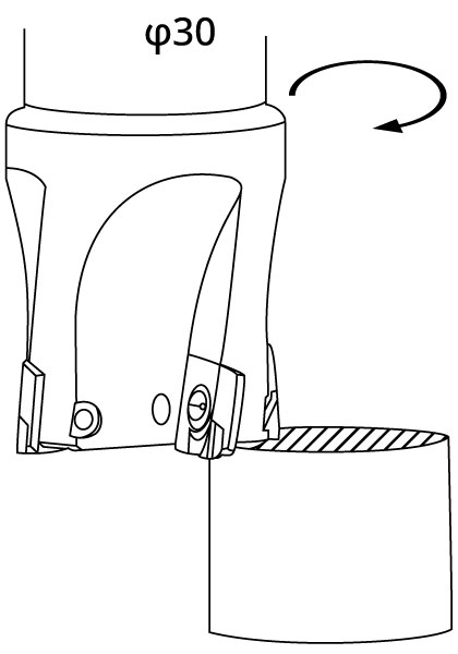
Cutting of under holder
Material :
A7000
Surface
roughness
standards :
12.5S
Surface
roughness :
6S
Cutting
specification :
φ 30 1.2” ×4 cutting edges (PD1)
φ 50 2” ×4 cutting edges (Competitor’s PCD)
φ 32 1.25” ×3 cutting edges (Competitor’s PCD)
Cutting speed :
750 m/min 2,400 SFM (PD1)
785 m/min 2,500 SFM (Competitor’s PCD φ 50 2” ×4)
700 m/min 2,300 SFM (Competitor’s PCD φ 32 1.25” ×3)
Revolution :
8,000 min−1 (PD1)
5,000 min−1 (Competitor’s PCD φ 50 2” ×4)
7,000 min−1 (Competitor’s PCD φ 32 1.25” ×3)
Feed :
0.1 mm/t .004 ipt
Table feed rate :
3,200 mm/min 126 ipm (PD1)
2,000 mm/min 79 ipm (Competitor’s PCD φ 50 2” ×4)
2,100 mm/min 83 ipm (Competitor’s PCD φ 32 1.25” ×3)
DOC :
ap=3,d=3,d=1.5
3 PASS (PD1)
d=0.4<br.
1 PASS (Competitor’s PCD φ 50 2” ×4)
d=3,d=3,d=1.5
3 PASS (Competitor’s PCD φ 32 1.25” ×3)
Coolant :
WET (external coolant)
PD1
24,000 pcs / corner (Ongoing)
Competitor’s PCD φ 50 2” ×4
10000 pcs / corner
Competitor’s PCD φ 32 1.25” ×3
2500 pcs / corner

No chipping of the carbide inserts occurred.
Due to good performance, the current φ 32 1.25” and φ 50 2” have been unified to φ 30 1.2” .

Cutting of rail frame (for two-wheel)
Material :
W2K
Machine :
Small M/C (BT30)
Cutting
specification :
φ 40 1.6” ×4 cutting edges (PD1)
φ 40 1.6” ×3 cutting edges (Competitor’s PCD)
Steel body
Cutting speed :
753 m/min 2,500 SFM (PD1)
314 m/min 1030 SFM (Competitor’s PCD)
Revolution :
6,000 min−1 (PD1)
2,500 min−1 (Competitor’s PCD)
Feed :
0.05 mm/t .002 ipt (PD1)
0.08 mm/t .003 ipt (Competitor’s PCD)
Table feed rate :
1,200 mm/min 47 ipm (PD1)
600 mm/min 24 ipm (Competitor’s PCD)
DOC :
2~4 mm .08~.16 inch (Multiple cutting)
Coolant :
WET
PD1
30,000 pcs / corner
Competitor’s PCD
10~20 pcs / corner

This cutter has resulted in a significant increase in lifespan and efficiency.

■Be sure to clean all the insert pockets before carrying out the following steps:

  • Step1: Preventative measures against insert chipping
    Attach a piece of adhesive tape (preferably, a tape low in adhesion) to the end of a dial gauge’s probe.
  • Step2: Mounting inserts
    For HPC: First, install the cartridges to the body, then, tighten each insert with the insert clamping screw at 3 N・m.
    【Caution: If you mount inserts in a cartridge first, it’s not possible to install the cartridges to the body.】
  • Step3: Temporary tightening (using a torque-wrench)
    Tighten set screw (1) first, at 4 N・m.
  • Step4: Setting
    While watching the reading on the dial gauge, rotate set screw (2) so that the insert with the highest cutting edge is lifted by +0.03 mm +.0012” . Next, with this position as the reference, set the cutting edges of all other inserts with variations in run out to stay within +/- 5 microns .0002 inches ( 10 microns .0004 inches in terms of range).
  • Step5
    Remove the probe from the dial gauge.
  • Step6: Tightening set screws (using a torque wrench)
    For HPC, tighten set screw (1) at 8 N・m

■Supplemental explanation

  • Even after the set screws have been tightened, the run out of the cutting edges should stay within approximately +/- 10 microns .0004 inches ( 20 microns .0008 inches in terms of range).
  • In the above case, NTK standard inserts (excluding some of them; see the note below for details.) and re-ground NTK inserts will not affect the tool life and surface finish.
HPC Fixed Type

No need for pre-setting

No need for cutting edge adjustments!
(The only requirement is clamping and unclamping of the inserts with the clamping bolt)

【Note】

The holes for the axial set screws and balance adjusting screws are filled with a special material, thus, no screwdrivers and hex-wrenches can be inserted in them.
※The color of the special material is different from the color of the actual product body.

Related News

For more information about this product, visit our online e-catalog, or download the catalog/product report

About
Solutions & Products