For turning small parts | Y-axis holder + KM1 Insert
Automatic lathe (Gang type) machining plastic materials (PEEK/PTFE, etc.)
Front turning (ISO) / Back turning / Grooving / Cut-off / Threading / Boring
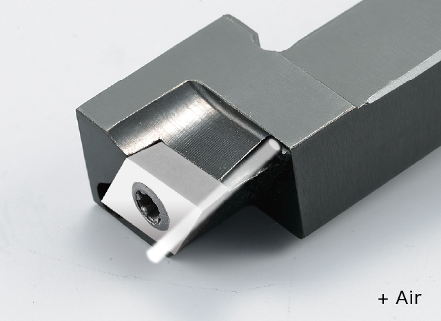
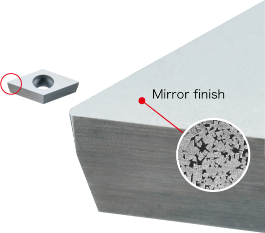
Excellent surface finish using an insert featuring an up-sharp edge and polished mirror-finish for welding resistance.
| Grade | Material | Operation | Machining | Cutting speed (m/min) Cutting speed (SFM) | Feed (mm/rev) Feed (IPR) | DOC (mm) DOC (inch) | DRY | AIR |
|---|---|---|---|---|---|---|---|---|
| KM1 | Plastic (PEEK,PTFE,etc.) | Turning | Roughing – Finishing | 50 – 150 164 – 490 | 0.05 – 0.10 .002 -.004 | 0.5 – 3.0 .020 – .118 | ● | ● |
| Medical implant | |
|---|---|
|
PEEK |
|
100 328 |
|
0.06 .0023 |
|
2.50 .010 |
|
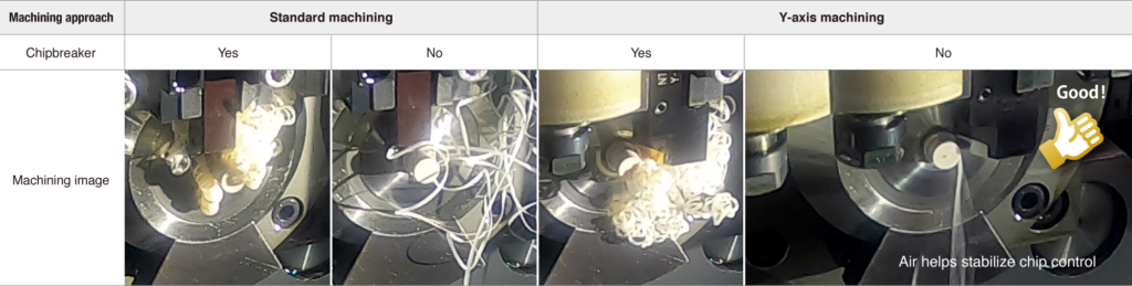
NTK:AIR Competitor:DRY |
| KM1 VCGT11T302H No chipbreaker |
80 pcs / corner
|
| Carbide VCGT11T302 Molded chipbreaker |
40 pcs / corner
|
| Automotive component | |
|---|---|
|
PEEK (with glass fiber) |
|
NTK:120
NTK:394
Competitor:40 Competitor:131 |
|
NTK:0.08
NTK:.003
Competitor:0.05 Competitor:.002 |
|
0.25 .010 |
|
NTK:AIR Competitor:DRY |
| KM1 DCGT11T302H No chipbreaker |
3 pcs / corner
|
| PVD Carbide VNMG160408 Molded chipbreaker |
1 pcs / corner
|
For more information about this product, visit our online e-catalog, or download the catalog/product report
Other recommend products