| Series | Features | DC | KAPR | APMX |
|---|---|---|---|---|
| mm inch | ° | mm inch | ||
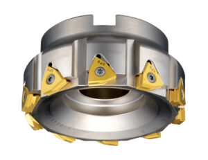
| JWNXM series |
Low resistance × multiple corners
|
⌀63 – 160 2.48 – 6.23 | 88° | -5.5 -.217 |
 |
||||
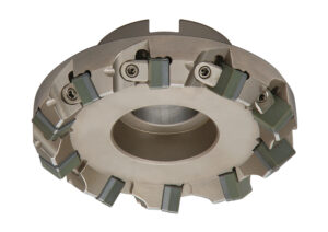
| JFDX series |
Low cost × versatility
|
⌀63 – 160 2.48 – 6.23 | 45°,75°,88° | -6 -.240 |
 |
||||
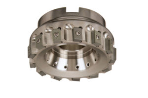
| JXTM series |
High rigidity
|
⌀80 – 125 3.15 – 4.921 | 88° | -8 -.315 |
 |
||||
| JQ series |
Shoulder milling × Small diameter cutter
|
⌀20 – 80 .787 – 3.15 | 90° | -8 -.315 |
-300x185.jpg) |
||||
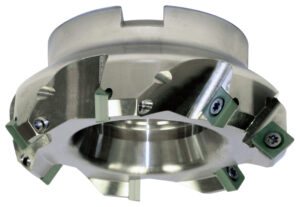
| JSDW series |
Low tool pressure
|
⌀80 – 160 3.15 – 6.23 | 45°,75° | -6 -.240 |
 |
| ISO | Work material | Coolant | Grade | vc (m/min) (SFM) | ap (mm) (inch) | f (mm/rev) (IPR) |
|---|---|---|---|---|---|---|
 |
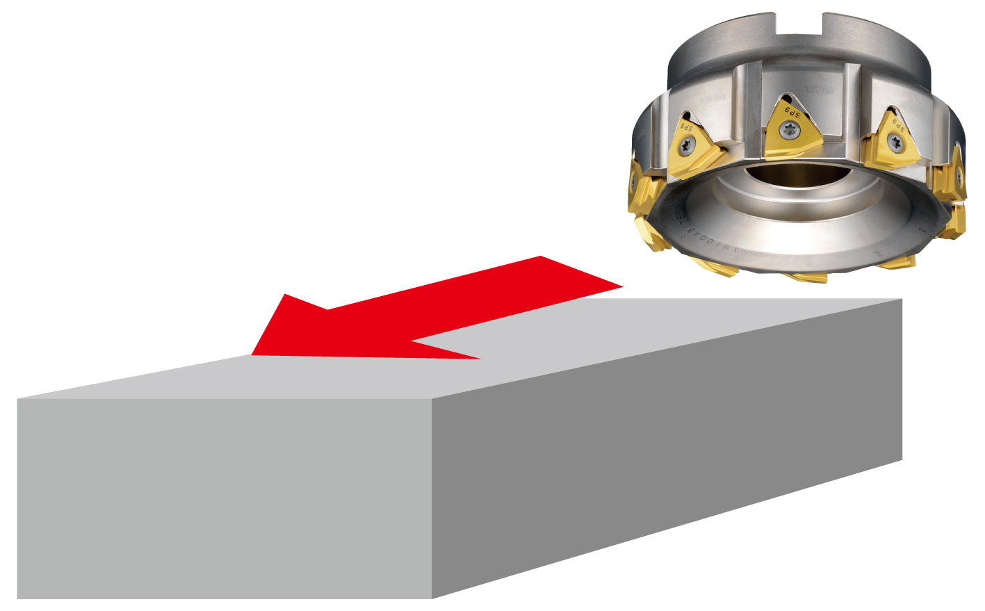
Cast iron Rough Milling |
DRY/WET | SX6 | 450 – 1200 1500–4000 | 0.5 – 3.5 .020–.140 | 0.07 – 0.2 .003–.010 |
| ISO | Work material | Coolant | Grade | vc (m/min) (SFM) | ap (mm) (inch) | f (mm/rev) (IPR) |
|---|---|---|---|---|---|---|
|
Gray cast iron Rough–Semi-finish Milling |
DRY | SP9 | 350 – 700 1150–2300 | -6.0 –.240 | 0.07 – 0.25 .003–.010 |
| Ductile cast iron Rough–Semi finish Milling |
DRY | 400 – 800 1300–2600 | -6.0 –.240 | 0.07 – 0.25 .003–.010 |
| Milling Application | ||
|---|---|---|
|
 |
|
|
||
|
||
|
||
|
||
|
||
| SX6 |
360 pcs / corner
|
|
| Competitor’s carbide inserts |
260 pcs / corner
|
|
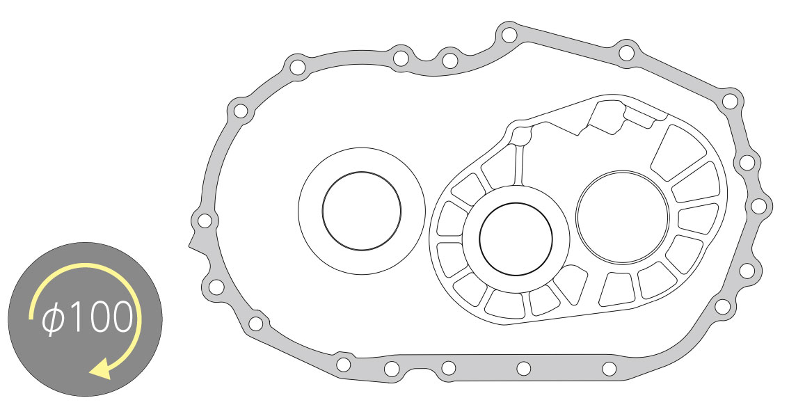
| Transmission Case Cover | ||
|---|---|---|
|
 |
|
|
||
|
||
|
||
|
||
|
||
|
||
|
||
| SX6 |
1.3 min
|
|
| Competitor’s carbide inserts |
5.4 min
|
|
| Transmission case | ||
|---|---|---|
|
 |
|
|
||
|
||
|
||
|
||
|
||
|
||
| SX6 |
120 pcs / corner
|
|
| Competitor’s carbide inserts |
60 pcs / corner
|
|