NTK Cutting Tools

Contact & FAQ

Contacts and Helpful Information

Home / Contact & FAQ

Contact Form

Insert Materials

For some shops, the flexibility of inserted carbide cutting tools might be too much of a good thing. “Carbide issafe and easy to use,” says Steven Howard, engineering and marketing manager for NTK Cutting Tools. Theproblem is that better-performing options can be easily overlooked—or worse, dismissed for the wrongreasons. “I’ve heard so many people say, ‘We tried ceramic cutting tools, but they didn’t work,’” he says. “Mostof the time it was because they were making mistakes.”

There are two main types of ceramics:
• Based on aluminum oxide or alumina (Al2O3)
• Based on silicon nitride (Si3N4)

Alumina (Al2O3) is the main component of ceramic, and is called white ceramic because of its color.
Titanium carbide (TiC) is added to alumina, and this is called black ceramic because of its color.
Whisker – It is a ceramic in which silicon carbide (SiC) is added to alumina.
Silicon nitride based ceramics can be divided into several types, according to content, mechanical properties.
SiAlON is a blend of Silicon nitride (Si3N4), Aluminum (Al), and oxygen (O)

In a broad sense, ceramics are a blend of metal or nonmetal with oxygen (O), nitrogen (N), carbon (C), etc., and this baked material is used as a cutting tool. The two main types are made by blending various additives to develop specific characteristics. Ceramics possess considerably higher hot hardness and chemical stability. This means that ceramics ensure much greater cutting speeds and wear resistance. Ceramics have higher fracture toughness
Ceramics are inherently hard and brittle therefore selecting the appropriate cutting-edge preparation is a factor of successful machining.

In many cases you can replace it with the same geometry and look for our DM4, QM3, or ST4 grades.
For some applications the cermet can be replaced with a ceramic grade.
Please contact an NTK representative and discuss the application if you are interested in ceramic option.

BIDEMICS is a patented material with unique physical characteristics that are above and beyond current whisker grades used on HRSA material applications. A combination of High Hardness, Superior Thermal Conductivity and Improved Strength results in significantly longer tool life to other industry standard grades used to machine heat resistant super alloy parts.

JX1 and JX3 – Roughing (no scale) / Semi-finishing in turning and grooving applications.
120 and JP2 – Finish turning applications

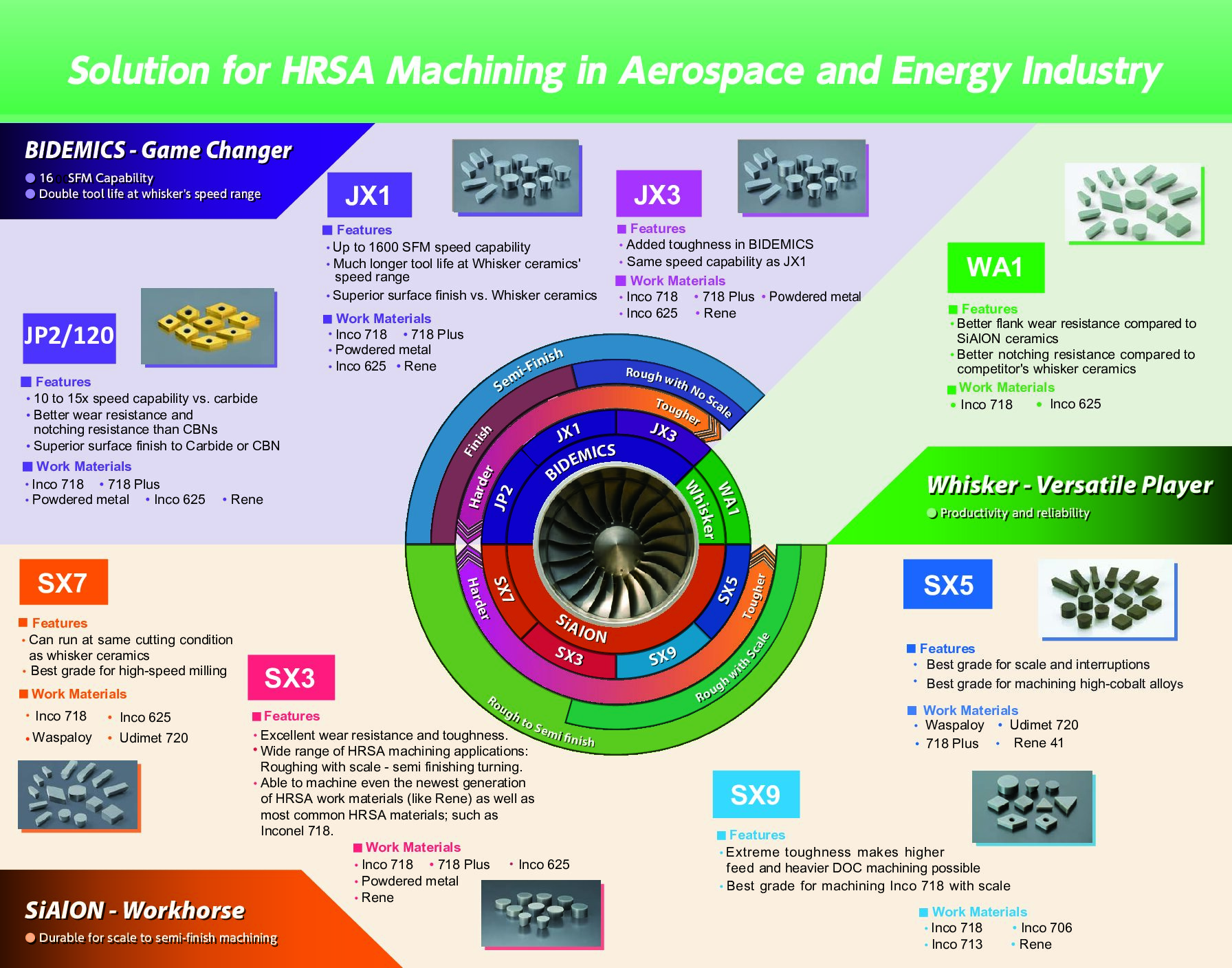
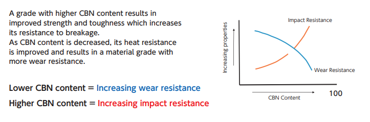
SiAlON ceramic is a silicon nitride based ceramic combined with“ Al” and“ O”. SiAlON ceramic offers excellent heat resistance, mechanical strength under high temperature, thermal shock resistance and wear resistance in addition to the toughness of silicon nitride. SiAlON shows superb performance in high speed machining of high temperature alloys.

SX3, SX5, SX7, SX9
Website Reference Material
HRSA Machining Catalog

Silicon nitride-based (Si3N4) ceramics have approximately twice the fracture toughness of alumina-based ceramics. Their fracture toughness is nearly the same as some carbide grades. Silicon nitride ceramic enables the user to perform productive high speed machining where traditional ceramic grades could not perform, including milling cast iron and interrupted cutting with scale.

YouTube Product Videos:

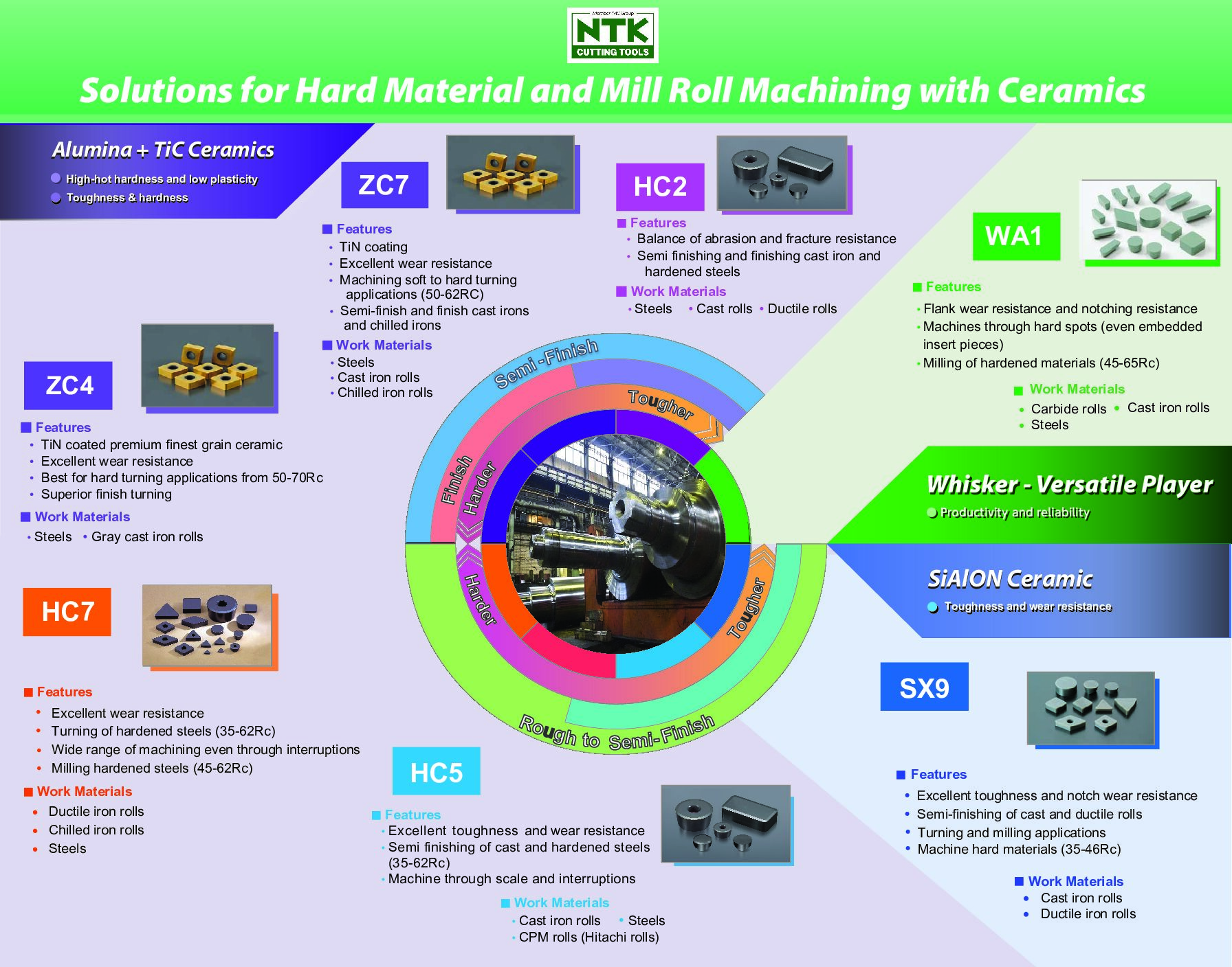
Alumina TiC-based ceramics are strengthened by adding hard carbide to highly pure alumina. The benefit of hardness and toughness enables the machining of partially interrupted cuts. This ceramic material has both high-hot hardness and low plasticity needed to turn steel, chilled or ductile iron rolls and some powdered metals as hard as 62 HRC. ZC4 grade can perform finishing cuts on steels up to 70 HRC. These ceramics are cost-effective alternatives for applications previously limited to CBNs.”
HC2, HC5 – chilled cast iron, steel, and powdered metal
HC7, and ZC7 (TiN coated) – carburized and induction hardened material
ZC4 (TiN coated) for hard turning finishing applications up to 70 HRC

HC6 is a TiC based ceramic with improved wear resistance used for finish turning of ductile/nodular cast iron parts.

WA1 is a whisker-reinforced ceramic material with Silicon-Carbide (SiC) whiskers added to alumina. WA1 machines HRSA materials at high cutting speeds and hardened steels with interruptions. Our whisker grade has a higher (SiC) content than competitor’s whisker-reinforced ceramics. The resulting material, WA1, shows increased productivity and extended reliability in applications where both toughness and notching resistance are needed.

WA1 is a good option for milling hardened materials (HRC 45 – 62)

Our SX5 is the toughest of our Sialon ceramic grades. Best for turning high-cobalt alloys, heavy scale, and interruptions.
Work Materials such as: Waspaloy, Udimet720, 718 plus, Rene 41

A tool material is the material that exists at the cutting edge of an insert. This is the material that directly cuts the workpiece during machining.

These material grades are manufactured using WC micro-grain carbide,
a hard micro-sized granulated material, to make up the insert substrate. Then the substrate is coated using a PVD method with TiN, TiCN, and/or TiAlN. ST4, DM4, QM3, DT4, TM4, ZM3, VM1, AC3
Uncoated carbide grade: KM1
Diamond coated carbide grade: UC1
The end results are materials that are suitable for precision machining and machining of difficult-to-cut materials.

Polycrystalline diamond (PCD) and Polycrystalline Cubic Boron Nitrides (PCBN) are the two hardest insert materials.
NTK PCD grades: PD1, PD2, and UC1 (diamond coated carbide)
NTK PCBN grades: B99, B30, B23, B36, B6K (Coated), B40, B52, B5K (Coated)

PCBN is a combination of CBN compound with a binder of ceramic that are sintered together. NTK CBN grades have various ceramic binders (TiN, Ti, TiC, or TiCN, or AlN), which feature outstanding heat resistance.

A grade with higher CBN content results in improved strength and toughness which increases its resistance to breakage.
As CBN content is decreased, its heat resistance is improved and results in a material grade with more wear resistance.

Our B40 grade is designed for severely interrupted cuts due to its exceptional toughness.

Developments in science and technology brought a new class of wear-resistant Nano layered coatings. These coatings are a combination of layers having a thickness of up to 50 nm (nanometers) and demonstrate significant increases in the strength of the coating compared to conventional methods creating a hard layer to extend tool life.
• TiN – adhesion resistance; abrasion resistance; resisting effects of high temps
• TiCN – wear resistance; resisting effects of high temps
• TiAlN – oxidation resistance; resisting effects of high temps

SiAlON ceramic grades blend the strength of silicon-nitride with the heat and wear resistance of alumina oxide. NTK has five grades (SX3 is the newest) featuring excellent strength and thermal shock resistance under high temperatures, as well as notching resistance. Ideal characteristics for high-speed machining of heat-resistant alloys common in aerospace, power generation and oil and gas industries. If you prefer to perform finishing operations with carbide, NTK offers DM4, QM3, and ZM3 grades. Our swiss tool offering is extensive to manufacture small HRSA parts.

Yes. Please review our grade charts for suggestions. The reference is based on grade comparison information.

It is important to note that an NTK associate may suggest a specific grade will be a better fit; based on the application.

Insert Designation

Edge preparations range from:
• FNX = up sharp edge (not recommended for ceramic)
• E = A honed edge. Protects ceramic from chipping or fracturing. (Feed rates must be > the hone size to ensure it is cutting)
• T = A chamfered edge (T-land). A common edge for ceramic. The cutting forces are distributed over a concentrated area of the insert edge.
• Z or S = A hone is added to a T-land which provides a strong edge to prevent chipping. For interrupted cuts or hard turning.
• J,P, & Q = 2 T-lands and a honed edge. Generally used in heavy roughing cuts or hardened turning. It is extremely shock resistant but does generate large cutting forces.

NTK Cutting Tools – Heat Resistant Alloy Tools – Catalog

The last 5 digits of a description refers to the type of edge preparation applied to the insert.

For example: CNGA 120408 432 T01025 T0425
T = a chamfered edge which has
010 04 = 0.1mm .004″ land width
25 = a 25 degree land angle
A larger edge example: CNGA 120408 432 S02025 S0825
S = a chamfer with a hone on edge
020 08 = 0.2mm .008″ land width
25 = a 25 degree land angle
A honed edge example: RPGN120400 RPG43 E004 E02
An up sharp edge: FNX (not recommended for ceramic)

NTK Cutting Tools – General Catalog

This identifies the number of edges on the insert.
PF is 1 edge
PD is 2 edges
PT is 3 edges
PQ is 4 edges
PH is 6 edges
PE is 8 edges
PBF is 1 edge with 3D chipbreaker

This indicates that the nose radius is 0.025mm .001″ smaller that described.

CCGT 09T302 32.508 M FNAM3 QM3 will have a 0.178mm .007″ nose radius
CCGT 09T302 32.508 FNAM3 QM3 will have a 0.2mm .008″ nose radius

We suggest to review the item section in our USA catalog and see if a similar insert is available in the same grade and edge preparation or chipbreaker with an acceptable alternate nose radius. Or, if the insert is available in the same geometry and grade with a similar edge preparation. Or contact us for suggestions.

Swiss CNC Applications

Using high pressure coolant improves machining with :
• Chip evacuation away from cutting edge and machined surface
• Reduced cutting temperature
• Improved tool life by Maintaining cutting edge sharpness
• Consistent part tolerance during production run

A combination of tool selection and techniques help to obtain ideal surface finish on the part.

• Increase the speed- this reduces built up edge to extend tool life
• Reduce the feed- to reduce flank wear and extend tool life
• Use an insert with a wiper – this allows you to either slow the feed to achieve a better finish or run at high feed and achieve a good finish. (indicated by a “WP” at the end of carbide insert description)
• Use a coolant through holder. The coolant is then directed at the cutting edge to evacuate chips – prevents chips from damaging the insert and part surface, keep the temperature constant which improves tool life      – keeping the insert sharp longer.

The answer is operation dependent. If you are looking at CCGT, DCGT, VCGT style inserts. YL , CL, and AM3 are good selections.

DM4 has excellent heat resistance and is the best choice for these materials. A alternate choice would be QM3 or DT4.

ST4 is our first recommendation for hard to cut stainless steels. Second choice is DM4.

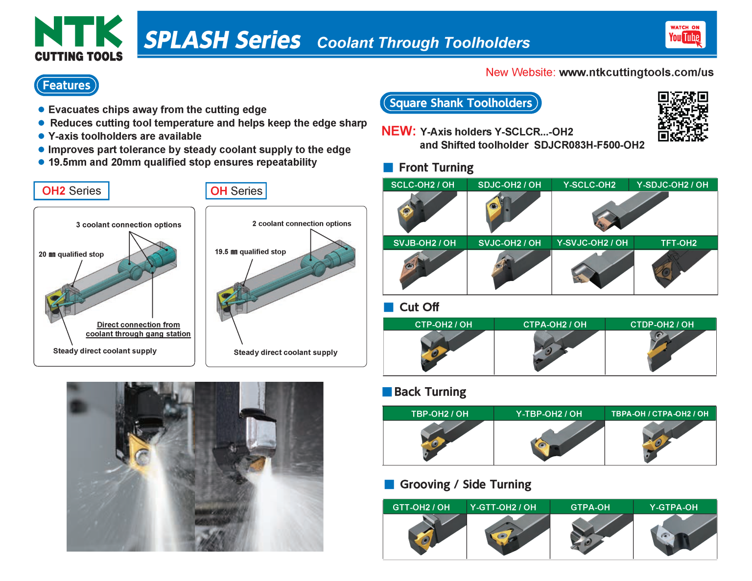
OH seen at the end of a description designates coolant through capability providing steady supply of coolant directed at the cutting edge. 2 coolant connection options and a 19.5mm .768” qualified stop.

OH2 seen at the end of a description designates our newest coolant through series providing 3 coolant connection options. The design incorporates a coolant connection for new coolant through gang plates on designated Swiss machines.

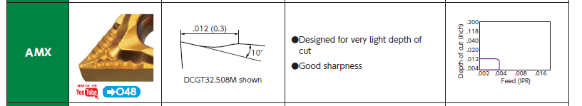
Our AMX chipbreaker is designed for thin chip control situations with exceptional sharpness.

Use an insert with our F -style chipbreakers. F1, F05, or FG. These are an exclusive design for ID boring to evacuate the chips backward. Use: RH insert with a RH boring bar and LH insert with a LH boring bar

We have a broad selection of unique chipbreakers that are designed for specific applications or operations.
If your machine has a vertical gang station we have a line of Y-axis holders that are the answer to chip tangling issues. The part is machined on the y-axis and chips drop away from the cutting edge and part.

A unique toolholder designed for machines without Y2 axis.
Centerline adjustment is possible by tool adjustment with a wrench. It eliminates center boss on the part end face. Provides constant OD dimension. Adjustment is simple even when tool is on the machine.

The TFX insert is designed specifically large depths of cut up to 5mm .197″ in a single pass. A wiper insert is also available for superior surface finishes.

There are advantages to each geometry and well as chip control and finish.

Socket Machining-Shaper Duo

Compared to End milling:
• Cycle times are reduced and there is no need for a high speed spindle.
Compared to Broach tools:
• Less tool pressure – especially on small diameter parts and one size insert (for Hex and Square socket) covers a range of socket sizes.

Once you have selected the shaper stick insert, identify the diameter of the insert (Ds). Choose the appropriate shank size holder from our selection of Stick duo sleeves and match the inner diameter value (Ød in the tooling chart) with the Ds dimension on the stick insert (also identified in holder description)

Example:

Holder: HY-NBH05020J-OH
05 = 5mm 5mm(= .197”) (a 5mm 5mm(= .197”) stick insert will fit)
020 = 20mm 20mm(= .787”) (shank diameter of holder)

We have compiled the set-up instructions, sample programming codes, and trouble shooting in our Shaper Duo brochure which is located on our website Media page under downloads.

The suggested parameters are based on machining 303 stainless. If you are cutting a harder material or harder to cut material, you should reduce the feed and the depth of cut per machine pass.
• Feed 1300 – 2500 mm/min 50 – 100 IPM
• Rough DOC 0.025mm .001″
• Finish DOC 0.005mm .0002″

For further assistance contact:
Send inquiry email to USA technical department

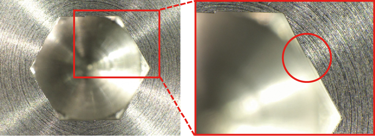
This is most likely caused by incorrect too set-up. (center-line shift)
Machine one angle and make sure both (a) and (b) lengths are identical; adjust the centerline height by rotating the sleeve tooling until you get the same length. (the difference should be less than 0.02mm .0008” )

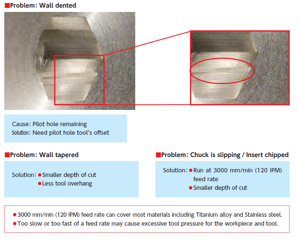
It is most likely that the pilot hole is still visible. So you will need to check the set up of the pilot hole.

To solve this issue, take smaller depths of cut which will increase the number of machine passes. And look at reducing the tool overhang.

Yes, we have a new selection of Hex style insert bars that range from 1.0mm .039” AF (range 1.0 – 1.1mm .039” – .043” ) up to 1.3mm .051” AF (range 1.3 – 1.4mm .051” – .055” )

If you are interested please contact your NTK Regional Sales Manager – Link to contact information

Thread Whirling

In order to provide a quote for our unique thread whirling system, please provide:
• A drawing of the thread form and lead of screw
• Workpiece material
• Bar stock diameter
• Swiss machine model number
• Whirling spindle number

Email Check list form and Drawing to technical support USA: NTK Inquiry

Grooving

Use the minimum possible overhang
Work with constant RPM SFM
Reduce the insert geometry in order to decrease the cutting force.

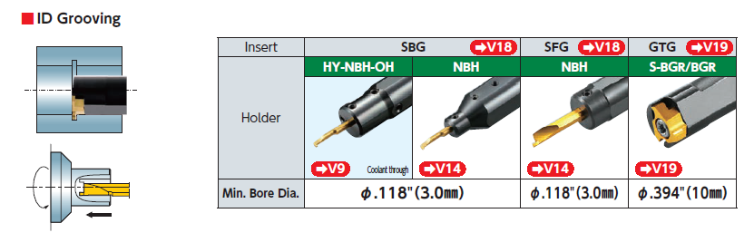
Our Stick Duo Series lineup SBG and SFG stick style inserts have minimum bore diameter of 3mm .118″ .
SBG for ID grooving
SFG for ID face grooving

Our BG series with GTG inserts has a minimum bore diameter of 10mm .394″

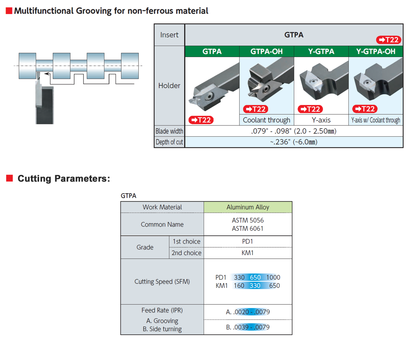
We carry GTPS series tooling a selection of holders and inserts in our KM1 carbide and PD1 PCD insert.

Our BIDEMICS, Sialon and Whisker ceramic grades are ideal in our VGW style inserts. The best grade is dependent on the specific material, conditions of the part being machined, and machine capability. SX7 is a good starting grade and SX3, SX9, and WA1 are second options. For Waspaloy parts SX5 will be the first choice in grades.
See our modular tooling in straight and L-style holder bodies. A broad selection of blades for profile grooving and face grooving can be utilized with the toolholder body options.

Yes, we have “Groove Duo” a line of modular tooling (holder bodies and various blades) to use with our VGW style inserts in BIDEMICS, and Ceramic grades for HRSA machining and Whisker for hard turning.
We also have a line of blades, GBWPF, that use a selection of DM4 carbide grooving inserts to machine HRSA, Titanium, Cobalt chrome, Steels, and Stainless steels. The GT chipbreaker is designed specifically for face grooving applications.

When ordering the L-style holder (GKWP) be sure to remember to use the opposite hand blade. ie. a right hand holder body GKWPR… takes a Left hand blade and vise versa.

Saturn Duo is a face grooving tool system with FGV type inserts for face grooving and FBV type inserts for face machining. 2 tipped inserts for economical solution. Improved tool rigidity by optimizing overhang and holder shape. Holders for gang-type, front-gang type, and sleeve holder styles available.

Being on center is very important when grooving. The cutting edge is presented at a 90 degree angle (unlike turning inserts). So, if you are above center the grooving inserts tends to rub on the flank rather than cutting the material efficiently. Being on center allows the material to come down on top of the cutting edge rather than at an angle. If you are going to miss the center it is better to be slightly below center rather than above center.


In this case if you take multiple grooving passes to generate the grooved area the insert edge may encounter a work hardened area during the last pass which may cause chipping or notching.
Instead, try plunging the grooving insert down both outside walls to ensure a good finish. The remaining material can be removed by using a stronger insert shape, such as an RCGX.

Milling

We recommend using a torque wrench to 4Nm 35lbs (4Nm) for most cutter series.

Our SX9 grade end mills are mainly applied to machining heat resistant alloys, heat resistant stainless steel, cast irons, and hardened steel (D2)

Link to reference material

No, do not use carbide tool paths for ceramic tools. It is best to use advanced machining CAM software programs to create smoother tool paths to achieve improved tool life and productivity with ceramics.

A continuous cut is recommended. An interrupted cut may cause chipping or breakage.
If using a hydraulic or shrink chuck, blow air at the arbor body to prevent heat expansion. Do not blow air directly at the endmill.
A minimum speed of 300m/min 980 SFM is required
A 1.5 degree ramping angle is recommended. Run at 50% lower feed rate during ramping cut.
Cutting HRSA materials:
Continue to machine even if you see BUE, removing BUE may cause chipping or breakage.
High speed machining work hardens the material. For this reason, leave at least 0.3mm .012” of material for a finish cut.

Yes, typically parts that are cast are more difficult to machine than forged parts. It is recommended to decrease feed rates by 25% on cast parts.
Maximize feed rates for gray cast iron.

Yes, we carry button cutters for RPG and RNG ceramic inserts in HC7 and WA1 grades. It is recommended to use large edge preparations.
RPIW cutters (RPG inserts) : 32 up to 80mm 5/8 up to 4.0 inch dia.

RNIW cutters (RNG inserts): 50 – 80 mm 2.0 to 4.0 inch dia.

*Reduce feed rates by 25% upon entrance and exit of the cut.
*Increase feed rates in corners to compensate for heat loss.
*As DOC get smaller speed should be increased to compensate for heat loss.

Unfavorable cutting conditions include:
1) workpiece with skin (siliceous or slag, for example)
2) significantly variable machining allowance
3) considerable impact load due to non-uniform machined surface
4) surface with high-abrasive inclusions

Unstable cutting conditions refer to the low stability of a complete system (machine tool, workpiece holding fixture, cutting tool, workpiece) due to:
1) poor tool and workpiece holding
2) high tool overhang
3) non-rigid machine tools
4) thin-walled workpiece

We carry a comprehensive range of indexable milling cutters, designed specifically for the efficient machining of aluminum.
The HFC series cutters – are high-quality lightweight body design with adjustable edge height, internal coolant supply, and our PD1 grade polycrystalline diamond (PCD) ground and polished inserts with different corner radii or chamfer options.
A PCD insert regrind and cutter rebalancing program is available upon request.

The HPC series of fixed and Adjustable type cutters – available in a wide range of diameters, insert selection available in PD1 and a PVD coated carbide TM1. Wiper feature and chipbreaker options.

In general, increasing the feed combined with a reduced depth of cut is a more favorable situation for MRR and improved tool life. But, this can depend on factors of the application.

No coolant should be used while milling with SX3, SX7 and SX9.

Chip thinning refers to decreasing maximum chip thickness hmax compared to feed per tooth fz.
Two factors cause this decrease:
1) Cutting geometry of a milling tool, specifically the insert cutting edge angle χr when it is less than 90° (“axial chip thinning”). Good examples of axial chip thinning are fast feed milling and machining 3-D surfaces at shallow depth of cut by ball nose or toroidal-shape milling tools.
2) Influence of width of cut “ae”. If “ae” in peripheral milling and face milling is smaller than the radius of the milling tool, hmax becomes lower than fz. This effect is known as “radial chip thinning”. Understanding chip thinning is very important. Maintaining necessary chip thickness requires appropriate increase of feed per tooth and is a key element for correctly programmed fz.

Ceramic tools behave differently than carbide tools. In most cases, the end of a tool life is determined by the acceptable level of burrs and not by wear size.

The term “chip load” is another term for “feed per tooth” or “feed rate”. In the past manufacturers referred to it as “table feed” which originates from a classic style milling machine where feed motion was created by movement of the machine table.

A wiper flat is a small minor edge on a regular indexable insert used in milling cutters to improve the quality of a machined surface. The ceramic milling inserts “with a wiper” must be installed in all the pockets of a cutter.
A wiper insert is specially designed were the wiper flat is significantly larger than on a standard insert. When mounted in a milling cutter, the wiper insert protrudes axially relative to the regular inserts. The CBN wiper insert height is relative to the lead angle of the cutter so it will effectively smooth the machined surface, noticeably improving surface finish.

One or 2 CBN wiper inserts can be installed in our cutters with ceramic inserts.

An insert clamping screw requires thorough visual examination before using a milling cutter. The threads and head of the screw, as well as the socket for a key, should all be in good operating condition. If the screw is damaged, or the screw is bent, the screw must be replaced immediately.
When tightening a screw, apply the correct tightening torque and use the right key to prolong the life of the screw.

The correct answers: At the end of the tool life or upon reaching the wear limit.
During a machining operation, there are certain signs that can indicate the need to replace inserts, or tools.
-Noticeable increase of power consumption (spindle load)
– Increased vibration and noise
– A decrease in the accuracy when machining and a need for frequent additional tool adjustment
– Reduced surface finish quality
– Formation of burrs or noticeable increase in burr formation
– Visual inspection of a cutting edge shows considerable flank wear, extensive edge chipping, or cracks

For question regarding identifying end of life of an insert for a specific application, we recommend contacting your NTK Regional manager, NTK Representative, or our technical dept.

Turning

Always use the strongest possible insert shape to maximize strength and productivity. Round inserts have the highest strength and V style (35 deg) inserts have the lowest.
If the application allows, the best is to use round inserts or square insert with a large nose radius and small entry angle.

Reference Material Link

As you cut a radius with a radius the interaction between the two can move. You will see that the point on the insert where the cutting is taking place will move around the insert. The programming and the insert is made to cut on the 12 o’clock position. As you move down the radius with the round insert that point moves to the 10 o’clock or 2 o’clock position. This causes push off and can lead to the final edge not having the tolerance you need. A simple solution to this is to use a smaller IC size insert which will move the engagement point of the cut closer to the 12 o’clock position.

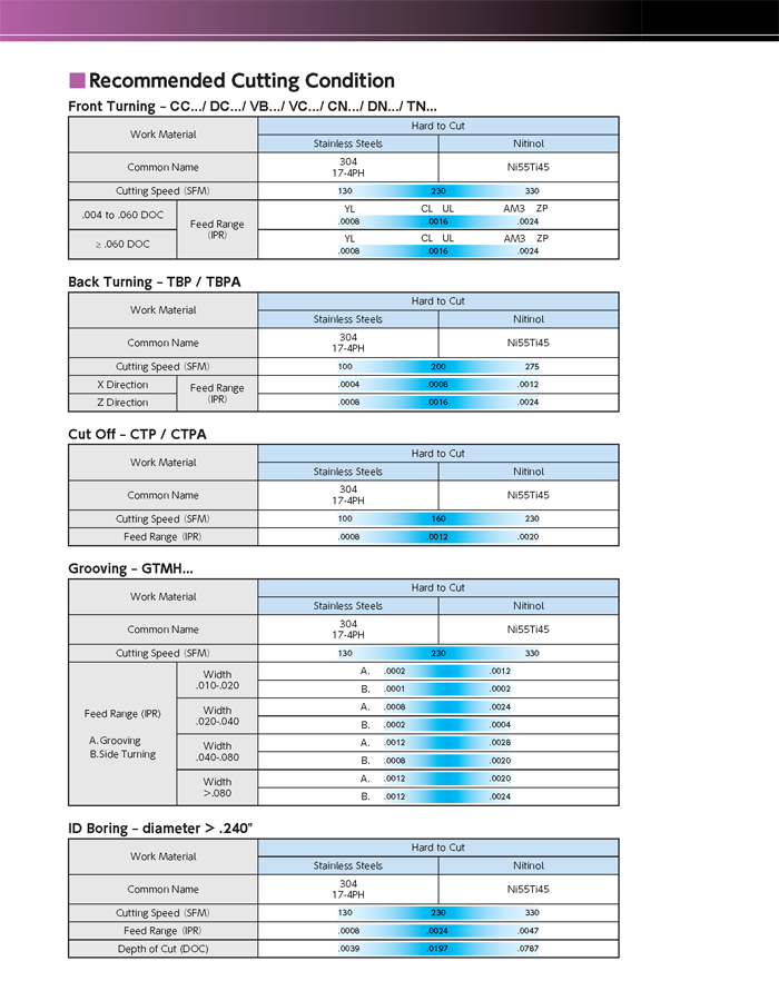
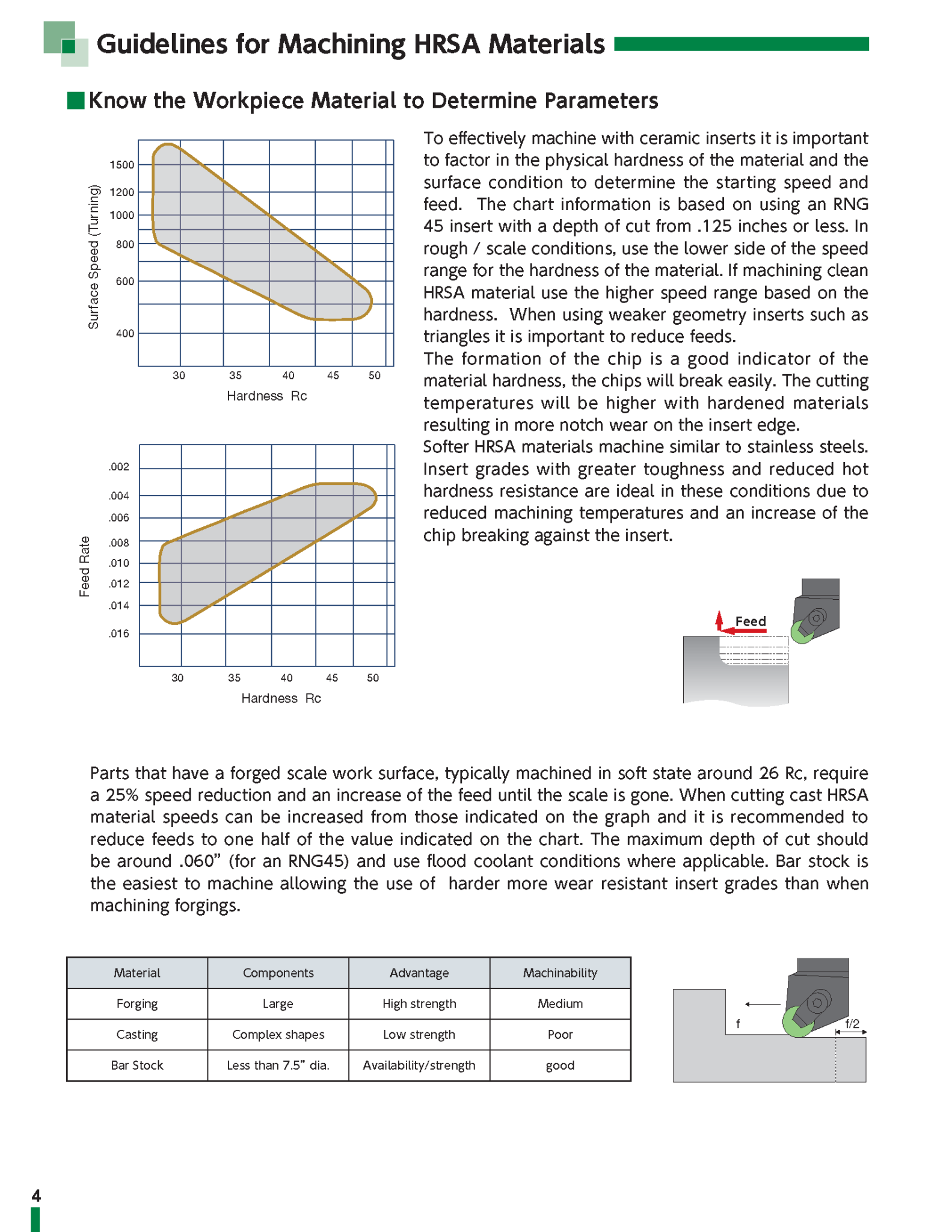
As part material hardness increases the machining cutting conditions should be reduced. If there is scale on the part the cutting conditions should be further reduced until the scale is gone.

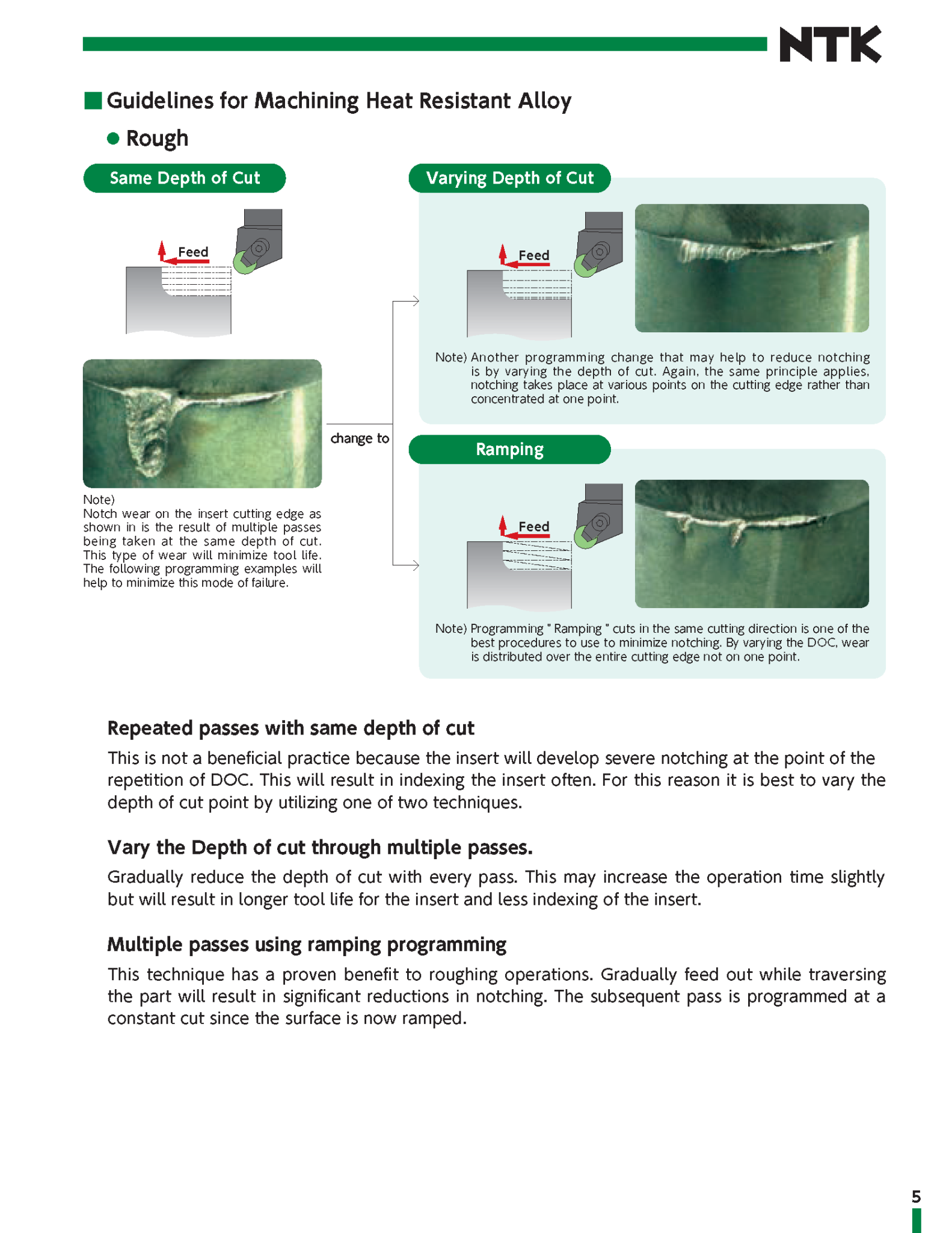
Instead of repeating machining passes at the same depth of cut try varying the depth through multiple passes. Gradually reducing the DOC with every pass may increase machine time but will result in longer tool life and less indexing of the insert. This process will move the wear on the insert edge.
Or, try multiple passes using a ramping program to significantly reduce notching on the insert.

Gray cast iron is recognized as the most popular material in the automotive industry. For rough machining gray cast iron, SX6 ceramic grade inserts are the number 1 choice. The main advantage is its wear resistance and thermal shock resistance (for wet turning or milling) making it possible to run at speeds three times faster than any conventional carbide inserts. This greatly increases productivity.
Turning speed range: 550 – 1100 m/min 1800 – 3500 SFM
Milling speed range: 460 – 1300 m/min 1500 – 4200 SFM

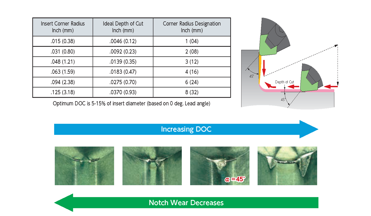
Any increase in DOC requires a reduction of the speed and feed rates. Parameters are based on the ceramic insert’s ability to withstand high temperatures and run with a chip thickness that allows the heat to be concentrated in the zone ahead of the insert resulting in low cutting pressure and minimal wear. If the speed is reduced without a corresponding reduction in feed, this effect will be lost and the performance will fall off due to chipping of the insert edge from a cooler chip.

Reference Material Link

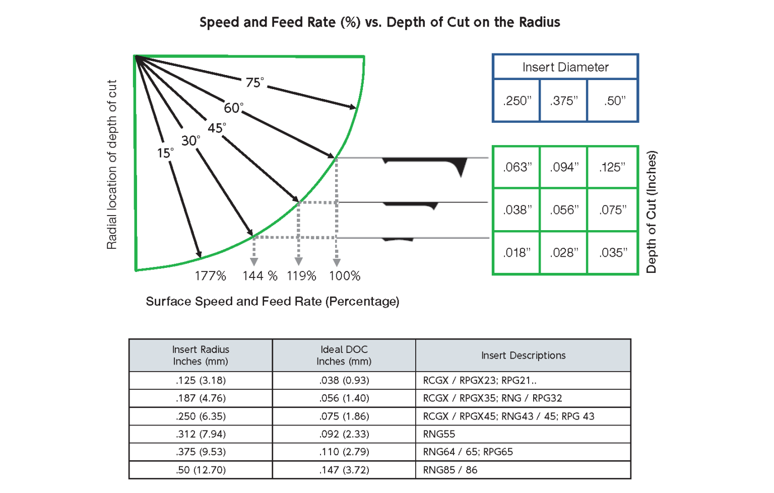
There is a correlation between the insert nose radius and depth of cut.

It is a good idea to decrease your feed rate by 50% going into corner and coming out of the corner after the direction change.

It is best to remove most of the material in the roughing operation with a round insert. The material removal amount for the finishing operation should be suitable for the nose radius on a straight edge insert. If the part has a required radius feature called out, then do not leave more than the amount of material called out for the required insert radius to finish the part and feature. By applying the correct nose radius on the finish pass and staying below the 45 degree mark of the corner radius, notching is minimized allowing a cutting operation to be programmed from both directions on the insert into the corner.

Reference Material Link

When turning with BIDEMICS, SiAlON and Whisker a flood coolant condition should be used. In some cases where a high interruption is encountered it may be best to shut off the coolant.
No coolant should be used while milling with SX3, SX7 and SX9.
Also note high pressure coolant delivery system is NOT recommended.

Use the largest lead angle possible to spread the cutting forces over a larger surface area of the insert. This will reduce notching for improved tool life and better surface finish.

This may happen when machining a part with scale or harder materials. The common cause is machining at too high of speed and feed. Parts with a forged scale require a 25% reduction of speeds and feeds until the scale is gone. Another solution is to pre-chamfer the part to reduce the potential for the insert to chip or break at the entry or exit point.

Refer to our chart relating insert nose radius – depth of cut – feed rate to achieve the best finish.

Recommended Feed Chart

Nose radius Depth of Cut ( mm inch ) Feed ( mm/rev IPR )
30 micro 60 micro
0.4 1/64 0.2 .007 0.05 .002 0.08 .003 0.08 .003 0.101 .004
0.8 1/32 0.4 .015 0.08 .003 0.101 .004 0.101 .004 0.127 .005
1.19 3/64 0.51 .020 0.101 .004 0.127 .005 0.127 .005 0.17 .0065
1.6 1/16 0.76 .030 0.101 .004 0.14 .0055 0.15 .006 0.2 .0075
6.35 1/4 2.03 .080 0.18 .007 0.25 .010 0.25 .010 0.36 .014

Look at using a stronger insert. A negative insert with a heavier edge preparation, chamfer and a hone for machining hardened steels and irons.

Look for at “S” edge preparations to help protect the edge: S0415, S0420, S0525, S0635

Workpiece Materials

BIDEMICS, Ceramic and CBN are not suitable for titanium applications. Ceramics are run at high cutting speeds which can be a fire hazard.
The best option is to look at our coated carbide grade inserts.

Recommended carbide grades: DM4, DT4, QM3, TM4, ZM3

Stellite is a group of hard cobalt chrome alloys which are difficult to machine. Sialon and whisker Grade suggestions will be recommended based on the application.

Work MaterialRough Turning / ScaleRoughing no scale & Semi-finishingGroovingMilling
1st Choice2nd Choice1st Choice2nd ChoiceHigh RPM Potential1st Choice2nd Choice1st Choice2nd Choice
Stellite 6SX5SX9SX9WA1JX3SX7SX3SX9SX7

Duplex stainless steel has a austenitic-ferritic metallurgical structure. Super duplex stainless steel contains an increased percentage of chromium and molybdenum to improve corrosion resistance. They are considered hard-to-cut materials.

Duplex stainless steel – 22cr Duplex (Duplex SS2205) – a ferritic and austenitic steel with 22% chromium, 3% molybdenum, 5-6% nickel alloyed stainless. (X2CrNiMoN22-5-3)

Super Duplex stainless steel – 25Cr Duplex (S32750; S32760; 2507; 2750; alloy 2507) has 25% chromium, 4% molybdenum, and 7% nickel. The high molybdenum, chromium and nitrogen content causes high resistance to chloride pitting and crevice corrosion attack. (X2CrNiMoN25-7-4)

Nitinol, or Nickel Titanium (Ni-Ti) alloy. It causes abrasion and oxidation wear on the cutting edge. Cutting speed affects tool life. If the speed is too low or too high the tool life drops dramatically.

material: Ni55Ti45
Grade suggestions: QM3 , and ST4

QM3, VM1, and TM4 carbide inserts are successfully applied to copper applications. UC1 grade has a ultra-fine grain coating of PCD.

Beryllium copper or BeCu, (Beryllium bronze or spring copper) has good machinability. It will be similar or slightly easier to machine than tool steels or most stainless steels. It is one of the highest strength copper based alloys. Alloy characteristics include excellent precipitation-hardening treatments, excellent thermal conductivity, and resistance to stress relaxation.
Two families:
C17200 & C17300 – high strength with moderate conductivity
C17500 & C17510 – high conductivity with moderate strength.

No, these are two different types of cast iron. Austenitic nodular iron is also referred to as ductile Ni-resist material. The presence of nickel, chromium, and copper make them corrosion-resistant. Parts machine similar to gray cast iron although insert geometries may be more closely related to those suited for austenitic stainless applications. The machinability is usually better than cast steel. The chromium content is the important factor effecting the machinability as chromium content increases the machinability is reduced because of the increase of hard carbides.
ADI pieces may vary in material condition and hardness levels that will impact the choice of cutting tools. A pre-hardened ADI part may machine similar to a high alloy steel material. If the casting is machined in a hardened state you need to look at tools used for machining “H” group cast irons.

“Pre-hardened steel” relates to steel that is tempered to a hardness that is not too high – generally less than 45HRC. The terms “pre-hardened” and “hard steel” are related to the ability of tools to cut the material. Steels can be divided into the following groups depending on their hardness:
Soft steel: annealed to hardness up to HB 250
Pre-hardened steel:
• HRC 30-37
• HRC 38-44
Hardened steel:
• HRC 45-49
• HRC 50-55
• HRC 56-63 and more

As for “hard steel”, usually it refers to steel hardened to HRC 60 and higher.

Mild steel is also known as low carbon steel. Less carbon means that the steel is typically more ductile, machinable, and weldable than high carbon and other steels. This however also means it is nearly impossible to harden and strengthen through heating and quenching. (1018, 1020, 1026, 1020/1026, CR 1045, HR 1045, 12L14, CR 1215)

Plastics have very good machinability. In comparison to metals, cutting plastics is performed usually with much higher speeds and feeds, and the cutting tools experience less wear. However, selecting appropriate cutting tools is essential to obtain the accuracy required and excellent surface finish. Selecting the appropriate cutting tools is essential to obtain the accuracy required and excellent surface finish. We suggest an up sharp insert with a grade that is adhesion resistant.
Chip control issues are common. If you are using a Swiss CNC with a vertical gang station, our Y-axis toolholders with eliminate chip tangling. Proper chip removal and cooling either air or a mild water-based coolant will improve heat removal to keep the insert edge sharp, improving tool life and maintain part tolerances. KM1 grade inserts are manufactured with very sharp cutting edges for shearing the material and a polished mirror finish for excellent adhesion resistance. Insert selection includes 0.0 radius options.

KM1: an uncoated carbide, precision ground and polished to a mirror
finish (adhesion resistance), and edge sharpness
TM4: Edge sharpness, thin coating, adhesion resistance

Check out our insert selection.
Carbides: KM1 reference, VM1, and TM4 reference

Vitallium is a cobalt (Co)-chrome (Cr)-molybdenum (Mo) alloy that contains approximately 60% of Co, 30% of Cr, 8% of molybdenum and some other elements. Vitallium was developed in the 1930’s, and is now used mainly in joint replacement surgery and dental implants. Its characteristics include high tensile strength. Fatigue and fracture resistance that is higher than stainless steel or titanium. The alloy is hard-to-machine. Cutting data should be set according to recommendations.

Dental implant applications

Carbide Insert Grades:
DM4 reference material
QM3 reference material

Generally, high-temperature aluminum is an aluminum alloy with more than 12% silicon content (A4032 or A2618). Typical applications include high performance pistons, Aerospace airframe and components. From a machinability standpoint , the high-temperature aluminum features considerable abrasiveness.
Check our selection of PCD inserts and tools
Grades: PD1, PD2
Grade: UC1 is a ultra fine grain diamond coated insert
Milling Cutters: HFC series and HPC series cutters

Nichrome is the name of a group of Nickel-Chromium alloys. It is also referred to as Chrome-Nickel, NiCr, Ni-Cr, etc. The well-recognized Nichrome 80 (Nichrome 80/20) is composed of 80% Nickel and 20% Chromium. Some Nichrome grades may contain additional elements such as Iron.
To machine Nichrome, the initial cutting parameters should be based on those recommended for Nickel-based super alloys.
Ceramic grade options: SX3, SX5, SX7, SX9 roughing and semi-finishing
BIDEMICS: JX1, JX3 (no-scale) semi-finishing
Carbides options: DM4, QM3

Yes, this is true.

Naval steels include various high-tensile, high-yield, alloy steels that are used mostly in marine applications, particularly for hulls of vessels and submarines. Typical representatives of these steels are 100 HLES, HY-80, HY-100, and others. The general approach to machining high-strength steels is based on recommendations regarding alloy steels with similar strength and hardness characteristics.

About
Solutions & Products